|
2016
2017
2014
Results obtained in Stage I
Design and obtaining of the nanomaterials
The "e-NOSE" project plans to create an "electronic nose" that can detect very low concentrations of pollutant and explosive gases. In order to obtain such a device, a microsensor matrix will be built, using miniaturized, silicon-based micro-transducers.
The project proposed that the microsensor matrix should use nanostructured materials with special morphologies, with large specific areas, which are one order of magnitude more sensible than "usual materials", capable of detecting very small quantities of gases.
The first stage of this project has proposed and accomplished the following:
- Design of the sensors;
- Design and manufacture of two masks and test structures;
- Design of the electronic blocks;
- Design of the sensor connectors;
- Obtaining the nanostructured films and powders with special morphologies (nanotubes and nanorods).
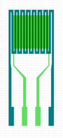
In order to achieve the objectives of this stage, the sensors have been designed onto silicon. A 600 nm Si3N4 membrane was used, which will further be released through anisotropic corrosion of the backside silicon.
Next, we established the layout used for the masks that are necessary in the technological process leading to the execution of the test sensor.
|
|
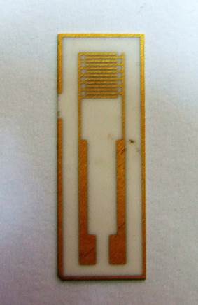
Fig. 1. Test sensor layout |
Fig. 2. Interdigital test sensor
on ceramic substrate |
This layout is obtained by superposition of two different layouts:
- a platinum resistor that acts as a heater and will be used in an early stage to test the alimentation voltage values, the application time, the temperature at the sensor surface;
- a Ti/Au interdigital capacitor (20nm/200nm) onto which nanostructured metallic oxides will be deposited with the purpose of testing deposition procedures and thermal treatment methods.
Using this layout, the masks necessary for the test sensors were obtained, through a technological process (Fig. 2.). The transfer of the layout image on the mask was accomplished using dedicated equipment, namely the DWL66fs equipment. Using the test mask, a capacitive test structure was obtained on ceramic substrate. The thickness of the Au film deposited on the ceramic substrate was 200 nm. The implementation of this test sensor on ceramic substrate will lead to measurements which will confirm the simulation data.
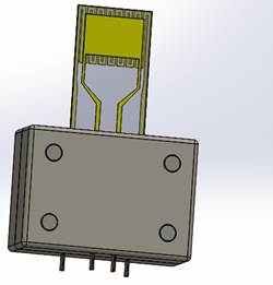
A special connector (Fig. 3.) which takes into account the pad dimensions and the distance between them and which holds up to 250oC was conceived for the alimentation and the registering of the signal from the gas sensor.
|
|
Fig. 3. Sensor-connector ensemble |
For the electronic interface used for the conditioning of the signal, the data measurement and acquisition, the project proposes two versions of the sensor platform: a mobile version and a fixed, laboratory version with multiple functions: signal detection and processing, data acquisition, transmission and interpretation, as well as setting off the alarm.
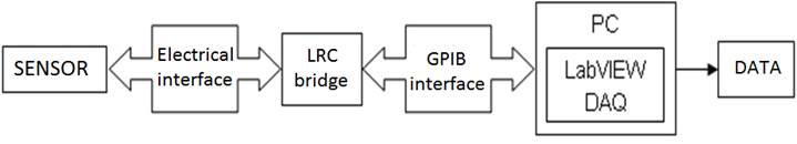
|
Diagram of the experimental set-up used in the electrical testing of the sensor |
|
Diagram of the integrated system containing the portable module which is interconnected with the calculator |
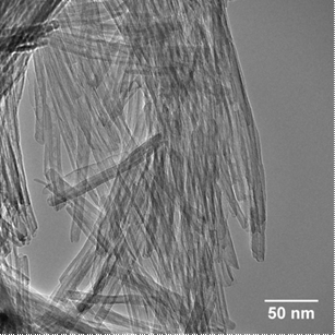
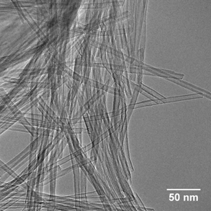
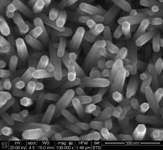
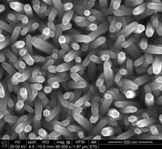
We obtained TiO2 and ZnO powders and films consisting of nanotubes and nanorods, respectively (Fig. 4 and Fig. 5). The thin films were deposited on glass, Si, ceramic and gold substrates. The films deposited on Si have been tested in a 37% HCl solution and those deposited on glass have been tested in a NH4Cl solution. Both solutions have permitted the corrosion at room temperature of the ZnO(N+In) through the positive resist mask.
(a) |
(b) |
Fig. 4. TEM images of the TiO2 nanotubes obtained through (a) hydrothermal and (b) hydrothermal + microwave methods |
 (a) (a)
|
 (b) (b)
|
 (c) (c)
|
 (d) (d)
|
 (e) (e)
|
Fig. 5. SEM images of the ZnO thin films deposited on (a) glass, (b) n-Si, (c) p-Si, (d) Al2O3 and (e) Au substrates |
CONCLUSIONS
In the first stage of the e-NOSE project, we have accomplished the design and manufacture of the test sensor layout, which will have an important role in the detection of very small quantities of pollutant and explosive gases.
The technological steps for obtaining the test sensor structure were established.
The test mask set was implemented, this being an intermediary step between the 2D design and the manufacture of the sensor. During this stage, we have obtained only test masks for preliminary tests of the sensor functionality.
With the help of the masks thus obtained and on the basis of the technological process previously mentioned, we have obtained a capacitive test sensor on a ceramic substrate, with the role of confirming the simulation data through electrical measurements.
TiO2 and ZnO powders and films with specific morphology (nanotubes and nanorods) were deposited on glass, Si, ceramic and gold substrates. The ZnO(N+In) films were corroded at room temperature through the positive resist mask.
2015
Stage two obtained results
Modeling, sensors manufacture, microstructures and electronic modules.
Nanostructured layers depositions
Stage two Objectives are:
O1. Modeling, sensors manufacture and microstructures
Sensor thermal modeling - report about modeling and thermal optimization of the sensors;
Sets of masks manufacture;
Microstructures manufacture;
Electrical and functional testing.
O2. Electronic modules manufacture
Manufacture of electronic modules - sensor testing module;
PCB design for signal processing electronic implementation, graphic interface design.
O3. Nanostructured layers deposition on sensor microstructures
Nanostructured thin layers deposition on sensor microstructures;
Layers characterization by XRD, AFM, SEM and SE.
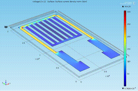
O1. The sensor’s heater modeling-simulation was carried out by using software tools based on finite element method. The heater design was gradually optimized, the final version allowing rapid heating of the substrate up to the desired temperatures, using usual voltages of 12-18 V.
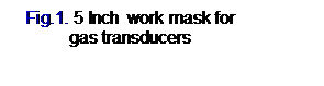
Sets of masks (Fig.1) were done in order to obtain microstructures on ceramic substrate by using a predefined technical flow on 4” ceramic plates.
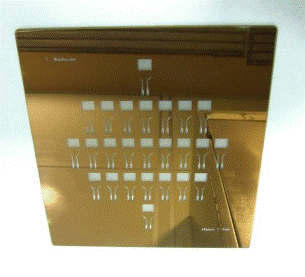
Transmitter and heater microstructures (Fig.2) were obtained on ceramic chips and after oxide layers depositions were tested as functional sensors, with own heating resistance integrated on chip, allowing to reach perfectly controlled working temperatures of 250 - 400 °C (by ranging the applied voltage).
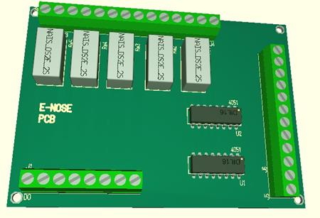
O2. The electronic module for sensor testing was manufacture (Fig.3) and entire electronics for signal processing together with graphic interface for process computer was designed.
Fig.3. Electronic module PCB - front view of the 3D scheme
O3. On the microstructures crafted on the ceramic supports thin oxide films were deposited by sol-gel (dipping and spinning) method in order to obtain nanotubes - based films (eg. TiO2-NT), or films with controlled porosity (eg. dopped and undopped ZnO, SnO2 and TiO2 - based systems). Oxide systems were afterwards sensoristic (electrically) tested inside a device with a continuous gas flow directed by a micro-controller - MFC. The electric answer of the deposited layers was measured at different gas concentrations (in the range 0 - 2000 ppm). The electrical resistance variation was recorded by a measuring deck RLC-HIOKI by applying a continuous voltage of 1.5 V onto the sample under test. The summary of the experiments is given in Table 1.
Table 1. Summary of the sensoristic results on the tested oxide films
Sample |
Deposition method |
No. layers |
TT (oC)-
time (h) |
CO |
C3H8 |
CH4 |
H2O |
ZnO |
dipping |
10 |
350oC-1h |
X |
X |
X |
- |
SnO2 |
dipping |
10 |
350oC-1h |
X |
X |
X |
- |
ZnO:SnO2(1:1) |
dipping |
10 |
350oC-1h |
X |
- |
- |
- |
SnO2:Zn(2%) |
dipping |
10 |
350oC-1h |
X |
- |
X |
X |
TiO2:V(2%) |
spinning |
5
10 |
300 oC-1h |
X |
- |
- |
- |
TiO2-NT |
spinning |
3 |
270oC-4 h |
X |
- |
- |
X |
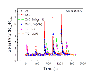
In Fig. 4 is depicted a comparison of the recovery time related to CO of all oxide systems put under the test. It can be observed that every one of them can offer a promising answer against CO and have a complete recovery, the signal returning to the baseline after each gas purge. Beside that, a series of gases like methane, propane and water vapors were tested. In Fig. 5 is given the comparison of two materials which presented sensitivity against humid air. It can be observed that the SnO2:Zn(2%) system has an extremely good answer (S = 55) and a complete recovery at room temperature. The TiO2-NT system has a much lower sensitivity (Fig. 5 inset) at the same temperature.
|
|
Fig. 4. Comparison of the response time of the tested materials against CO |
Fig. 5. Comparison of the response time of the tested materials against water vapors. The TiO2-NT response against CO is detailed in the inset. |
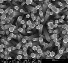
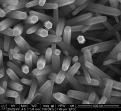
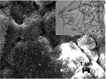
One of the challenges of this project was the obtaining of nanostructured films at low temperatures (from energy saving considerations, but also imposed by the danger of exfoliation of Au micro-circuits at high temperatures). The nanostructuring property was emphasized for all studied oxide materials, both by SEM and AFM, as the following example show for TiO2-NT deposited on interdigital ceramic substrate (Fig. 6).
|
Fig. 6. SEM image of the TiO2-NT film deposited on interdigital ceramic microchip. The inset illustrates the 1D behavior of the TiO2 powder in the “as prepared” state |
Not least, a portable device was designed for processing the signals received from the sensors. The main component of the device is represented by an industrial computer on which will be installed a software application specially developed for:
• maintaining the sensors at the optimal working temperature;
• collecting the data form the sensors;
• saving the all data into a database;
• to provide the data to an external user.
A controller with a color display interrogates in turn acquisition modules and ensures the local interface. This equipment has also installed a software application, which assure the data collecting and displaying. In order to avoid communication errors between the two controllers (the industrial computer and the display) and slave equipment (data acquisition module), a gateway is inserted in the electronic scheme.
In order to ensure the optimal temperature for the sensors, a power supply is connected to the two heating terminals of each sensor through a two channel relay. The relays are commanded by the industrial computer through a control module provided with digital outputs. On the surface of each sensor is present a thermocouple which transmits the data through an acquisition module with inputs for thermocouple towards the industrial computer.
As respects to data collecting from the sensors, the two measuring terminals of the sensors are connected to a multiplexer. The multiplexers outputs are connected to the resistance and capacitance measuring module. The outputs of the measuring module are taken by an acquisition module with analog inputs and sent to the industrial computer.
The connectivity of all modules from the portable device is ensured by a PCB, designed according to device functional description.
A project of the local interface was obtained, which will display the current values of the gas concentrations, particular alarms for gas presence or for gas limits exceeding, the date and the hour.
CONCLUSIONS
• Heater’s mask layout modification was achieved in order to ensure an increase of the heating temperature of the substrate.
• A new set of mask was achieved in order to obtain the new resistive type structure.
• The technological steps necessary to obtain the gas sensor structure were established.
• By means of obtained masks and the mentioned technological processes a number of 150 gas sensor chips on ceramic substrate were processed, with an efficiency of 60%, resulting a number of 90 good chips.
• The electric testing of the gas sensor was achieved with the help of a dedicated measuring device.
• A testing and characterization gas sensors electronic module was achieved (sensitivity, response time, stability in time of its characteristics).
• The design of a portable device for signal processing from the sensors was achieved. The final cost of the device was taken into account.
• A PCB was designed, according to device functional description.
• The design of the local graphic interface was achieved. A simple interface achievement was taken into account, but eloquent, useful both for normal environmental conditions and for alarm detection situations (the presence of gases or gas limits exceeding).
• One of the challenges of the present project was to achieve nanostructured sol-gel films both on glass and silicon substrates and also on micro-sensors supports, which lead to improved sensoristic results; the nanustructured nature of the films was emphasized in all cases by SEM and AFM analyses.
• Continuous and adherent, undoped and doped ZnO and TiO2 based films were successfully deposited by sol-gel method (dipping and spinning) on Au micro-sensors crafted on alumina supports.
• All the ZnO based films were receptive to CO, undoped ZnO and SnO2 films were receptive to methane and propane, and TiO2 films were receptive to water vapors.
• A noteworthy result is the low working temperature in testing the gases of interest (250-300 oC).
2016
SUMMARY
Electrical and functional testing
The project proposes the achievement of an “electronic nose” for detection of extremely low concentrations of pollutant and explosive gases.
The aim of this subject is micro-climates monitoring (houses, factories, cars, schools, shops, etc), alarming in case of dangerous concentrations, which will lead to an increase in security and safety of their inhabitants.
The objectives of Stage 3 are:
- Electrical and functional testing
- Participation to scientific events
- Large scale dissemination of the results
RESULTS
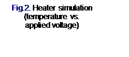
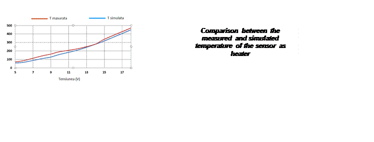
- Heater characterization and testing
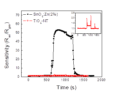
By applying a voltage on the heater pads and reading the temperature values obtained by heating the resistor, a comparison between the measured and simulated temperature was achieved, results indicating a very good correlation between data sets, as evidenced by the figure below.
- Detector apparatus fabrication
The hardware of the gas detection device was achieved. The main component of the device is represented by an industrial computer. Beside the connection ways offered by the computer, the device provides also a controller with color display, which interrogates in turn the acquisition modules and ensure the local interface.
- Electrical and functional testing of the sensors
The functional testing of the measurement equipment made by Romelgen was also achieved. As a consequence, a series of tests were performed in order to demonstrate the functionality of the “electronic nose”, on a gas sensor type which was previously functionalized by depositing several types of layers on the interdigital electrode surface.
To validate the values from the portable device, measurements were conducted simultaneously with the tests on the measuring bridge. The gas detection was obvious in both cases.
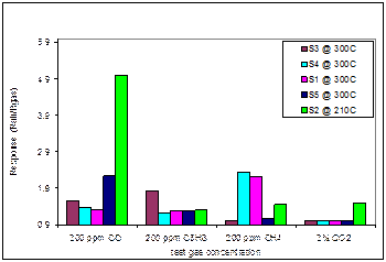
Electrical measurements performing on intrinsic sensitive materials (SnO2-ZnO based compressed powders in the shape of a tablet), and on microsensors obtained in the previous stage (transducer + sensitive film containing TiO2 nanotubes or SnO2-ZnO combinations) was another accomplished objective in the third stage.
The final shape of the investigated sensitive material was to be either a ceramic cylindrical tablet, or a thin film (SnO2-ZnO, TiO2-NT) deposited on miniaturized transducer.
The electrical measurements on the samples were performed in ambient conditions, inside enclosures with controlled atmosphere, with a gas flow directed by a mass flow controller – MFC. The electrical response of the tablets or of the thin films was measured at different concentrations of:
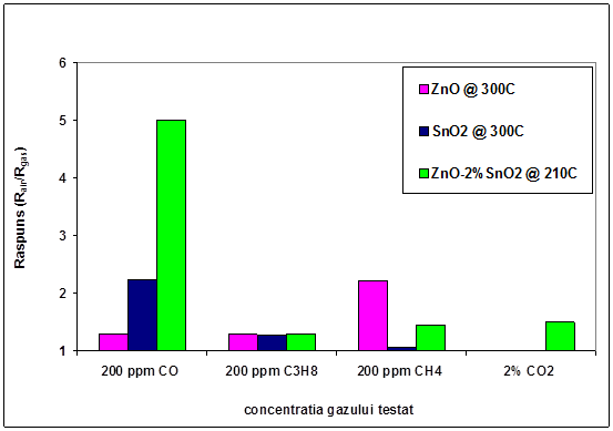
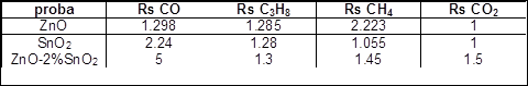
- Carbon monoxide (CO), methane (CH4), propane (C3H8) in the range of 5-2000 ppm, for the sensitive tablets and films with the composition: S1-100%ZnO; S2-98%ZnO-2%SnO2; S3-50%ZnO-50% SnO2; S4-2%ZnO-98% SnO2; S5-100% SnO2.
(Fig.7-for films)
|
|
Fig.7 Sensor cross-response of at the optimum working temperature |
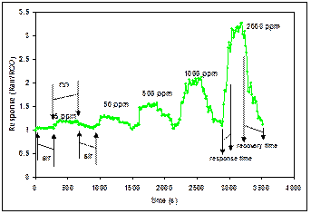
Fig.8 S2 sensor response and recovery characteristic at 3000 C, for different CO concentrations |
The results of the running tests showed that both types of sensitive materials (tablets and films) detects CO selectively in ambient conditions and the material response is influenced by the composition of the sensitive material, by the concentration of the analyzed gas and by the working temperature [1-3].
The recovery of these materials is complete during a measuring cycle, the response / recovery times are shorts and vary according to investigated sensitive material [1-3].
References
- P. Chesler, “Oxides with gas sensing properties”, PhD Thesis, Bucharest – 2016
- P. Chesler, C. Hornoiu, S. Mihaiu, C. Vladut, J.M. Calderon-Moreno, M. Anastasescu, C. Moldovan, B. Firtat, C. Brasoveanu, G. Muscalu, I. Stan, M. Gartner, Beilstein J. Nanotechnol., submitted-under review, 2016
- P. Chesler, C. Hornoiu, S. Mihaiu, C. Munteanu, M. Gartner, “Tin-Zinc oxide composite ceramics for selective CO sensing”, Ceram. Int. 42 (2016) 16677-16684
2017
THE SUMMARY OF THE STAGE 4 / 2017 – Electrical and functional testing – final part
4.0. Reproducibility of measurements made on CO and humidity sensors
4.1. Evaluation report of sensor module functionality
4.2. Workshop organizing
4.3. Elaboration and publication of the scientific and technical novelties
4.4. Patenting
This year the electrical and functional testing of the sensors was continued. The following structures were tested:
- new series of sensors synthesized according to the preparation route of the most efficient sensors obtained in the frame of the project, based on SnO2 and ZnO combination, where it was found their perfect reproducibility
- new sensors with active phases based on unforeseen materials in this project, such as: La(OH)3, LaCoO3, TiO2-Cu, BaSnO3, Pd and Ag doped SnO2. These sensors were additionally prepared in order to increase the number of sensors selective to CO, CO2, CH4 and C3H8
The functional testing was performed in this year’s workshop organized by IMT, thus achieving the most important objective of the project.
SCIENTIFIC AND TECHNICAL DESCRIPTION HIGHLIGHTING THE STAGE RESULTS AND THE ACHIEVEMENT DEGREE OF RESULTING OBJECTIVES AND THEIR DISSEMINATION
The most sensitive films prepared during 2015–2016 for CO, CO2, CH4 and C3H8 detection, as well as those prepared in 2017 (using materials less studied in the literature) are listed in the Tables 1 and 2. These films were obtained by using an economic and ecological alternative method (dip-coating or spin-coating sol-gel). The tables also contains beside the film deposition type, the thermal treatment performed in order to stabilize the sensitive film, the working temperature (Tw), the gases to which the films are sensitive and if the film could be considered as selective or not. For sensor preparation different substrates were used (porous alumina and silicon wafers). Based on results obtained from various tests, it was established that the porous alumina is the optimum substrate for the intended purpose.
Table 1 Films synthetized in 2015–2016
Sample |
Deposition type |
Film stabilization
(°C / h) |
Tw
(°C) |
Sensor response |
Selectivity |
CO |
C3H8 |
CH4 |
H2O |
CO2 |
ZnO |
Dip-coating
|
350°C - 1h
|
300 |
|
|
|
- |
- |
YES |
SnO2 |
300 |
|
|
|
- |
- |
YES |
ZnO:SnO2(1:1) |
295 |
|
|
- |
- |
- |
NO |
ZnO:Sn(2%) |
210 |
|
|
|
|
|
YES |
SnO2:Zn(2%) |
300 |
|
|
|
|
- |
NO |
70%Sn-20%Zn-10%Fe (SnZnFe1) |
Spin-coating
|
600°C - 8h |
290 |
|
|
|
- |
- |
YES |
50%Sn-20%Zn-30%Fe (SnZnFe2) |
600°C - 8h |
330 |
|
|
|
- |
- |
NO |
TiO2:V(2%) |
300°C - 1h |
295 |
|
- |
- |
- |
- |
NO |
TiO2-NT |
270°C - 4h |
250 |
|
|
|
|
- |
NO |
Table 2 Films synthetized in 2017
Sample |
Deposition type |
Film stabilization
(°C/h) |
Tw
(°C) |
Sensor repsone |
Selectivity |
CO |
C3H8 |
CH4 |
H2O |
CO2 |
La(OH)3 |
Manual application |
400 |
300 |
|
|
|
- |
- |
NO |
SnO2-3%Pd |
Manual application |
450 |
300 |
|
|
|
- |
- |
NO |
SnO2-2%Ag |
Dip coating |
350 |
300 |
|
|
|
- |
- |
YES |
LaCoO3 |
Dripping |
300 |
300 |
- |
- |
- |
- |
- |
NO |
TiO2-Cu |
Spin coating |
300 |
300 |
- |
- |
- |
- |
- |
NO |
FeWO3 |
Dripping |
200/300 |
200/300 |
- |
- |
- |
- |
- |
NO |
BaSnO3 |
Spin coating |
300 |
300 |
|
|
|
- |
- |
YES |
BaSnO3 |
Dip coating |
300 |
300 |
|
|
|
- |
|
NO |
SnO2-10S |
Dip coating |
900 |
300 |
|
|
|
- |
- |
NO |
Selectivity is the biggest challenge of the project and at the same time the biggest problem raised by the literature of this area. The selectivity describes the degree to which a senor responds only to the desired species, with very low or zero interferences from other species. Our samples can be considered as selective if the following approaching is respected:
- the synthetized samples (Table 1) are sensitive to all 4 gases of interest, but mostly to CO. In order to obtain a specific warning to the rest of the gases we worked by differentiation. We will explain this concept by an example.
If a sensor is sensitive in the same time to CO and CO2 and another sensor is sensitive only to CO:
- and the warning occurs to both sensors together, the detected gas is CO
- and the warning occurs only to the first sensor, the detected gas is CO2
The same concept was applied to the sensors made for methane and propane detection.
In Tables 1 and 2 the samples that are considered as selective are marked, while in Fig 1a and Fig 1b this behavior is exemplified on sensors based on SnO2-ZnO and SnZnFe.
|
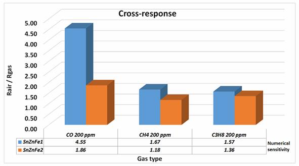
|
Fig.1 Selectivity of the samples based on: (a)SnO2-ZnO; (b)SnZnFe1 and SnZnFe2 |
4.0. Reproducibility of measurements made on CO and humidity sensors
In 2017 was continued and finalized the electrical and functional testing, started in 2016, of the sensors with the best sensitive films. The reproducibility tests were performed on a number of 10 samples deposited in the same conditions as the first sample deposited initially in 2015.
4.0.1. Reproducibility of sensors based on ZnO+2%SnO2 which were the most sensitive to CO detection
The sensor with 98% ZnO + 2% SnO2 have a selective response to CO at a Tw = 210 °C, with a small response time (120 sec) and a totally recovery of the sensor in 280 sec. The sensor based on SZFe2 has a similar selective response as the previous one, but at a higher working temperature, Tw = 330 °C.
The sensors are able to detect very low concentrations of CO, of about 5 ppm, for a long time after their preparation (1 year), which it proves the film stability in time (Fig. 2). This fact represents a difficult condition to satisfy in the sensor practice. The results are reproducible for Sn-Zn bio-component sensors, having the best selectivity to CO (Table 3).
Table 3 Sensory characteristics for 10 samples of ZnO+2%SnO2 deposited in identical conditions (the optimum working temperature 300–305 °C; lowest concentration 5ppm; highest concentration 3000 ppm)
Sample |
Sensitivity at: |
Recovery time (s) |
5 ppm |
50 ppm |
500 ppm |
1000
ppm |
2000
ppm |
1 |
1.35 |
1.40 |
1.85 |
2.40 |
3.90 |
180-230 |
2 |
1.30 |
1.41 |
1.79 |
2.25 |
3.54 |
180-250 |
3 |
1.28 |
1.40 |
1.79 |
2.55 |
3.90 |
170-240 |
4 |
1.37 |
1.40 |
1.66 |
1.99 |
2.77 |
130-230 |
5 |
1.50 |
1.58 |
1.92 |
2.44 |
4.02 |
120-220 |
6 |
1.18 |
1.25 |
1.60 |
2.07 |
3.16 |
154-176 |
7 |
1.53 |
1.74 |
2.38 |
3.20 |
5.51 |
176-220 |
8 |
1.18 |
1.25 |
1.60 |
2.09 |
3.42 |
120-190 |
9 |
1.59 |
1.75 |
2.30 |
2.95 |
5.02 |
156-200 |
10 |
1.20 |
1.27 |
1.64 |
2.17 |
3.34 |
120-220 |
Fig. 2. The response of 10 microsensors based on ZnO+2%SnO2 films deposited on
Au/Pt/alumina transducers for CO detection – the response is reproducible
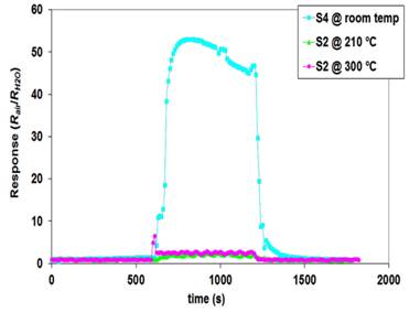
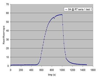
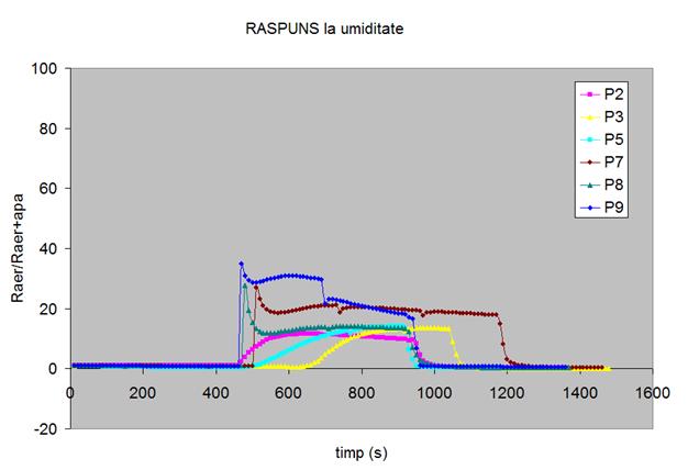
4.0.2. Reproducibility of sensors based on SnO2+2%Zn which were the most sensitive to humidity (water vapors) detection
The response to humidity is considered reproducible in the given working conditions: the working temperature is the room temperature, decontamination of the sensitive surface from preexisting humidity is impossible. If the test would take place at a working temperature much higher than the room temperature, a better decontamination of the sensor surface from environment pre-adsorbed humidity would take place, thus the response reproducibility being improved. However, this approach involves higher energy consumption, an important economic disadvantage in achieving a commercial sensor.
Fig. 3 The response of SnO2+2%Zn based sensors: (a) prepared in 2015 vs. 2016 (P1)
(b) all sensors prepared in 2016 (P2-P9)
4.1. Evaluation report of sensor module functionality
In Stage 4 of the project, the electrical and functional testing of the gas sensors has been achieved. Following the performed tests, the functionality of sensor module and its utility in detecting multiple gases was demonstrated. To achieve all the goals of the project IMT Bucharest provided the technological support required for all electrical measurements. Thus, in this stage a number of 12 wafers of 4″ were technologically processed on ceramic substrate. After this process a number of about 200 interdigital gas sensors were obtained. These sensors were used in resistive electrical measurements, in order to demonstrate their reproducibility and functionality in the presence of target gases. The most of the electrical measurements were performed at ICF, on the testing and data acquisition stand made by Romelgen.
Together with the measurements conducted in ICF, IMT performed a series of resistive electrical measurements in a Carbon monoxide containing environment, controlled by a high precision gas analyzer, which is able to detect and measure CO gas concentration between 0 and 4000 ppm, with a resolution of 1 ppm. The point of these parallel measurements was to prove one more time the reproducibility performance of these sensors, together with their functionality in real environments, namely in air.
The multiple testing made with commercial equipment and the comparison of these values with those obtained by the testing module developed inside this project has the role to validate the project, meaning the validation of the microsensor array and the attached electronic module.
|